


We are a world leader in high precision optical manufacturing, delivering custom optics to a wide range of innovators around the globe. Meeting these goals demands the right people. Teamwork, adaptability, and an enthusiastic approach to problem-solving are central to the Optimax culture. But what unites all our employees best is a hunger to continuously learn. We strive to find driven individuals who are committed to lifelong learning; who will continue to add value in their work throughout long and successful careers.
PRODUCTS & CAPABILITIES
Aspheric Optics
Optical systems integrators rely on Optimax to deliver high-quality aspheric lenses with the most precise focusing properties. Precision asphere manufacturing requires the right technology and know-how. We have one of the largest teams of technical experts in the industry, with years of experience tackling critical issues in aspheric lens manufacturing. Our unique expertise in specifying, manufacturing, tolerancing, and measuring aspheres allows us to develop innovative and collaborative partnerships with our customers, adding the maximum value to end-users.
Our aspherical lenses enable optical designers to overcome the intrinsic aberrations associated with spherical lenses, and to reduce system size and weight, ultimately leading to optical setups that are more compact and efficient than conventional systems. Optimax specializes in manufacturing high-quality aspheric lenses; leading the way with unmatched investment in cutting-edge equipment and testing, this allows us to develop deeply collaborative partnerships with our customers, adding maximum value to end-users.
REQUEST A QUOTE
Our quotes are structured to offer standard pricing and delivery – quicker delivery options are available upon request.
LEARN FROM THE EXPERTS
Discover how Optimax is changing the future of optics, and view our extensive library of resources.
JOIN OUR TEAM
We are looking for individuals that are committed to lifelong learning and creating value through their hard work.

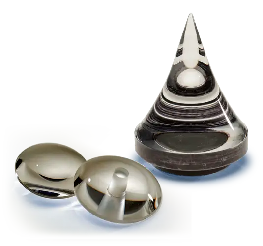
What is an Asphere?
An asphere is an optical element with one or more aspheric surfaces – a complex surface with non-constant curvature. These unique geometries have the ability to impart superior performance to optical systems by mitigating spherical aberrations. For imaging systems, aspheres enable clearer, sharper images. Additionally, a single aspheric optic can often be used in place of multiple optical elements, allowing for smaller and lighter systems.
Specifying Aspheric Optics
Specifying an asphere begins with a custom aspheric form, often fit to the Forbes Q Polynomial (Figure 1) or the Even Aspheric Equation (Figure 2).
Describing form involves specifying Vertex Radius (I/C). Conic Constant (k) and applicable Aspheric Coefficients (a). Including a Sag Table (Figure 3) provides reference information to check correct data entry for each manufacturing or metrology tool used. We accept asphere designs from our customers in manufacturing drawing format or by optical design software files (preferably, Zemax).
Our team is well versed in providing manufacturability feedback and providing cost and lead time trade-offs for various tolerancing schemes. If you have a question about your design, don’t hesitate to contact Optimax.
Forbes Q Polynomial
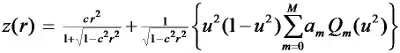
Figure 1
Even Aspheric Equation
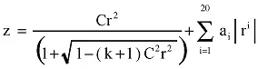
Figure 2
Sag Table

Figure 3
Manufacturing Aspheric Lenses
The foundation of our optics manufacturing expertise is the breadth of our metrology knowledge. After all, as the old adage states, “if you can’t measure it, you can’t make it.” Our metrology solutions range from industry-available tools to Optimax-built systems, including custom interferometric test set-ups, stitching interferometry, non-contact and contact profilometers, and high-precision CMM instruments.
A wide range of manufacturing platforms accompany this wide range of metrology tools – again, industry-available and Optimax-built tools for aspheric grinding, polishing, deterministic finishing, and smoothing. This wide range of solutions allows us to provide customers with high-quality, precision aspheres with few limitations.
FIND THE OPTIC SPECIFICATIONS RIGHT FOR YOUR NEEDS:
Asphere Manufacturing Limits Asphere Tolerancing Limits Manufacturing Tolerance ChartTechnical Expertise
Do you want to learn more about our optical manufacturing innovation? Refer to our Knowledge Center to read technical papers on, aspheres, business leadership, coatings, freeform optics, innovative optics manufacturing, and lens tolerancing & inspection.
Manufacturing the Future
At Optimax, we are manufacturing the future, creating the highest precision optics underlying high-tech systems in key markets and applications. We offer rapid and expedited delivery upon request and are committed to our customers in the long term.
Submit an RFQ to start building your relationship with one of the world’s foremost manufacturers of custom optics.