We are a world leader in high precision optical manufacturing, delivering custom optics to a wide range of innovators around the globe. Meeting these goals demands the right people. Teamwork, adaptability, and an enthusiastic approach to problem-solving are central to the Optimax culture. But what unites all our employees best is a hunger to continuously learn. We strive to find driven individuals who are committed to lifelong learning; who will continue to add value in their work throughout long and successful careers.
REQUEST A QUOTE
Our quotes are structured to offer standard pricing and delivery – quicker delivery options are available upon request.
LEARN FROM THE EXPERTS
Discover how Optimax is changing the future of optics, and view our extensive library of resources.
JOIN OUR TEAM
We are looking for individuals that are committed to lifelong learning and creating value through their hard work.
What are Cylinder Lenses?
Cylindrical optics are a type of lens with a curvature in a single direction, yielding different radii in the X and Y axes. Optical cylinders are subsequently ideal for condensing, focusing, or expanding incoming light. Optimax fabricates cylinders from a range of materials, utilizing a deterministic CNC machining process to ensure predictable removal rates and tight adherence to critical tolerances.
The surface curvature of cylindrical optics is typically spherical and they tend to have a plano-convex or plano-concave design, coming in circular, rectangular, or square profiles. These are used for a broad range of applications across the full spectrum of industry and research. Common uses of cylindrical lenses include correcting astigmatism and altering the shape of laser beams prior to collimation.
OEMs rely on optical cylinders for various purposes in holography, optical spectroscopy, laser line scanning, and more. Those same OEMs depend upon Optimax to overcome critical manufacturing challenges and to routinely deliver the highest quality cylindrical optics.
Specifying Cylinders
Several key parameters must be defined when specifying cylindrical optics, namely a tolerance for the radius – or power – axis and the plano – zero power – axis. Manufacturers must also define decentration in both axes, and the alignment of the optical axis with the mechanical one. Irregularity and slope may also be specified.
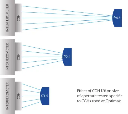
Optimax cylinder lenses are verified using interferometric techniques, including distance measuring interferometry, plano reference flats, and CGH diffractive elements. The latter converts the plane wavefront from a transmission flat to a cylindrical wavefront, which can be used to measure both concave and convex surfaces. The available coverage varies greatly based on the size and shape of the cylindrical surface.
For more information on CGH nulls and an illustration of available coverage please see:


Manufacturing Cylindrical Optics
Cylindrical lenses comprise an optical surface that has a radius in one direction and is flat in the orthogonal direction. The manufacturing methods used in cylinder manufacture account for this axis, subsequently conserving position. There are two primary production techniques used to fabricate cylindrical optics – the Arbor process and the X-Y process.
The radius of curvature divided by diameter – or width – gives an R-number, which helps define which technique should be selected. Alternatively, order quantity may be the determining factor in method selection. At Optimax, we pride ourselves on delivering a collaborative service, offering customers the benefit of our extensive expertise and assisting with the burden of choice.
FIND THE OPTIC SPECIFICATIONS RIGHT FOR YOUR NEEDS:
Cylinder Manufacturing Limits Cylinder Tolerancing Limits Manufacturing Tolerance ChartTechnical Expertise
Do you want to learn more about our optical manufacturing innovation? Refer to our Knowledge Center to read technical papers on, aspheres, business leadership, coatings, freeform optics, innovative optics manufacturing, and lens tolerancing & inspection.
Manufacturing the Future
At Optimax, we are manufacturing the future, creating the highest precision optics underlying high-tech systems in key markets and applications. We offer rapid and expedited delivery upon request and are committed to our customers in the long term.
Submit an RFQ to start building your relationship with one of the world’s foremost manufacturers of custom optics.


