What's it about?
Optimax Systems Inc. improved reliability of legacy asphere polishing platforms, preserving niche capabilities at a demonstrated level. In asphere manufacturing, key tools have evolved over the years. While not as capable, older technology is able to create useful surfaces, and, for some geometries, still represented the best option. Select work waited for older machines being repaired over and over. We set out to find a modernized version of these polishing platforms. We found we could not only match the results of the 20+ year old technology, but also surpass its functionality.
1. INTRODUCTION
As we looked into replacing this antiquated technology, we first had to determine what aspects of the older platform made it such a success, and kept it as a go to piece of technology for asphere manufacturing. The negative aspects of this machine also had to be addressed, as we wanted to improve on the shortcomings for our replacement. With the combination of positives and negatives, it gave us a clearer picture of how we could create a platform that would not only perform to the abilities of the antiquated machine, but also would allow the technology to grow as the company grows with higher volumes of surfaces to create, more challenging geometries to account for, and tighter tolerances on surfaces.
1.1 Positives of the antiquated polishing machine
This piece of equipment was used for more than 20 years and had been a key piece of machinery when it came to the processing of many aspheric optics, specifically for crystal materials such as silicon and germanium. These materials can be temperamental at times, yet this piece of equipment was capable of dealing with them and creating surfaces that not only met the specification for the overall form, but they also left surfaces that did not show extreme surface defects. This aspect of those antiquated machines was very important for my team to recreate because of the post processing that we are currently doing on the optics that come off of these antiquated machines. They are post processed with our Magnetorheological Finishing (MRF) machines and a surface defect free, close to final form optic is what is needed in order to ensure more effective finishing.
The size of the machine was also of great importance to us. As the company grows and our demand increases, real estate on the manufacturing floor has become increasingly valuable, so our replacement also had to follow suit and be at least comparable in size, so that the replacement could fit into the space of the antiquated machine.
The polishing style allowed for removal rates across the part to be highly predictable, leading to shorter correction times and fewer runs in order to do so. This combined with the ease of use of the software allowed for the optician to be able to make informed decisions when manufacturing the optical surfaces. In order for our replacement technology to be considered a success, we would also have to create a software package that would go along with the physical machine.
1.2 Negatives of the antiquated polishing machine
With this antiquated technology being more than 20 years old, the issue that occurs is that their parts are beginning to fail. Whether it is the motors that control the motion or it is the computer boards themselves, these parts are getting harder and harder to find in order to keep our machines running.
The first issue is that the antiquated machines are no longer supported by the original manufacturer. Servicing these machines then has to be done by our internal maintenance department, which has worked for the majority of the past 20 or more years. At the time of this publication, we had about three of these machines on the manufacturing floor that see frequent use, with six more of them in storage that are being used for spare parts as we see the “better” of these machines slowly breaking down. Cannibalizing dead machines for parts again has been a great short term solution to this issue, however this cannot be sustained and Optimax is already starting to see the end of this sustainability. At the beginning of this year, there were five of these machines in frequent use with four in storage that were used for replacement parts and since two have been moved from manufacturing to storage.
The second issue is that with the age of the machine also comes the age of the software and computer system that are attached to it. The computer runs Microsoft Windows ‘98 which creates problems for our modern network systems, which don’t allow for it to interact with the rest of our network. This means that any corrections that need to be applied to the optics have to be downloaded onto an external thumb drive, and uploaded to the computer, instead of the network access that the rest of our machines share.
1.3 Measures of success - replications
In summary, here are what we were looking to replicate from the antiquated polishing platform.
- Hold crystal surfaces to less than one micron of form error
- Motion of the machine had to follow the form of an aspherical optic
- Software needed to be user friendly and intuitive as well as control the machine correctly
- Optical Surfaces need to be ready for our finishing process
- Relative compactness of entire platform similar in size to antiquated polishing machine (roughly fit inside of a 3 foot by 6 foot rectangle)
1.4 Measures of success – improvements
Along with the replications from the antiquated polishing machine, there were also improvements that we wished to make.
- Reliability of the components
- Serviceability of the components
- Locational accuracy of the machine in respect to the calibration and rigidity of the platform
- Increased removal of material
2. ROBOTIC POLISHING PLATFORM
From the measures of success listed in Sections 1.3 and 1.4, we were able to come to the conclusion that a robotic polishing platform was the correct direction for us to go in finding a replacement. Robots have been used at Optimax since 2014 as part of our polishing process and we have become very familiar with how to correctly and safely operate them as a polishing machine.
2.1 ABB IRB 1200 6-axis robotic arm
From our experience with robots at Optimax, we knew that quite a few of the measures of success mentioned in Sections
1.3 and 1.4 could already be met. The robot in question that we decided to go with for our replacement was the ABB IRB 1200. This arm could handle optics up to 400 millimeters and still allow us to have a small platform only being roughly 4 foot by 4 foot. This does not exactly fit our requirements but still is close enough in size that we would only need to make minor adjustments on the manufacturing floor for this machine to fit. With the purchase of a brand new robotic arm, we also knew that any of the parts needed in the immediate future would be readily available and serviceable as well. If a newer, more attractive model of robot came out in the future, we could easily purchase the newer arm to replace our previous one, giving us the ability to use this platform for a very long time.
Being able to calibrate the robot is also included in the purchase of a new robotic arm so we also knew that the locational accuracy and rigidity of that calibration process was something that wouldn’t have to be solved in the scope of this project. From the manufacturer as well as through our internal research we had already created methods for calibrating the working area and the tooling needed for polishing.
2.2 Software development
With my experience with these robotic polishing platforms, I had also created software so that we could directly control the machine from a laptop computer, giving the user an easy and accessible way to use the robot as a polishing platform. This software is proprietary to Optimax and has been developed with the help of people on the manufacturing floor so that it could be tailored with the end user in mind and give them the control that they want. This software gives the user the ability to import asphere prescriptions, decide what parts of an optic they wish to polish, control feed rates and spindle speeds for optimal polishing as well as a correction software for changing the overall form error.
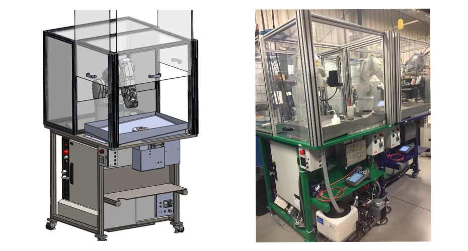
| Figure 1 Solid model of robotic polisher | Figure 2 Actual build of robotic polisher |
3. COMPARING ROBOTIC AND ANTIQUATED POLISHING PLATFORMS
After designing the base, enclosure, and tooling for the robot to use, we purchased the robotic arm and began running tests in order to determine the overall comparability of the robotic polishing platform versus the antiquated polishing platform. We already knew from previous tests on other robots (FANUC brand robots instead of ABB) that we previously had on the manufacturing floor that we were able to justify the cost of buying a brand new robotic arm, but what we didn’t know was how this new arm would compare specifically. Figure 1 and Figure 2 show the solid model and the actual build of the robot respectively.
3.1 Setting up the experiment
We set out to test this by taking a few asphere prescriptions that would be good averages of what our Prototype Aspheres group would see on a daily basis. This included a mixture of materials and geometries.
- Silicon 40mm Diameter Inflected Asphere
- Germanium 60mm Diameter Convex Asphere
- ZnS – MS (Cleartran) 60mm Diameter Concave Asphere
These materials and geometries were chosen as a good variety of parts which come through our Prototype Aspheres group fairly often as well as being optics that we knew the antiquated polishing platform would perform well on.
To start off each of these experiments we would be using similar tooling, feed rates, spindle R.P.M.’s as well as slurry types so that we could be as conclusive as possible. The only difference that was being tested was the robotic polishing platform’s performance as compared to the antiquated polishing platform.
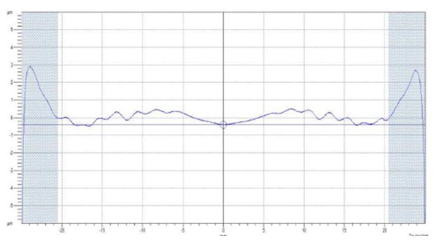
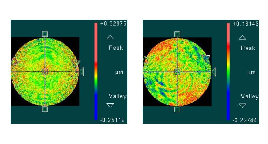
Figure 3 Antiquated Polisher Performance
PV: 0.9954 µm Polish Time: 30 minutes
RMS: 0.2738 µm Finishing Process Time: 60 minutes
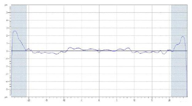
Figure 4 Robotic Polisher Performance
PV: 0.9053 µm Polish Time: 20 minutes
RMS: 0.2166 µm Finishing Process Time: 40 minutes
3.2 Silicon 40mm diameter inflected asphere
After completing the first part of our test, we saw very promising results as can be seen in the comparison of Figures 3 and 4. Both show a similar overall form error of less than one micron of peak to valley (PV) form error. We can also look at the root mean square (RMS) to see that they are also very similar. We look at the RMS value because this tells us more about how the form deviates from the surface in terms of how quickly the slope can change overall. The most promising aspect of all this is looking at the machine times between Figure 3 and Figure 4. The Robotic Polishing Platform was able to not only polish the optic faster, but it left a better surface that took less time in our finishing step than the Antiquated Polisher.
| Figure 5 Antiquated Polisher Performance | Figure 6 Robotic Polisher Performance | ||
| PV: | 0.495 fringes | PV: | 0.404 fringes |
| RMS: | 0.052 fringes | RMS: | 0.036 fringes |
| Polish Time: | 60 minutes | Polish Time: | 30 minutes |
| Finishing Process Time: | 90 minutes | Finishing Process Time: | 60 minutes |
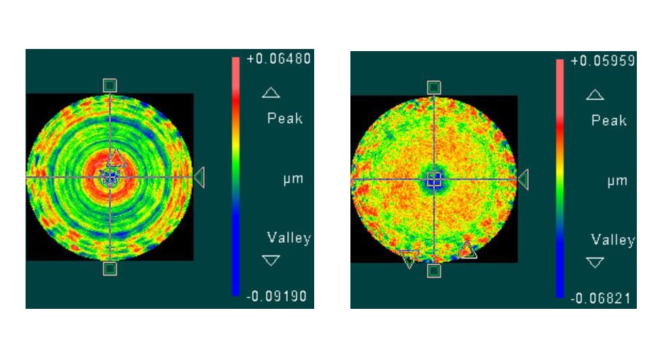
3.3 Germanium 60mm diameter convex asphere
With the Germanium samples, we saw very similar results as we saw with the silicon inflected asphere. This again was promising. Showing that we can not only do this on one material, but we can continue to perform at or above the level of the antiqued polisher on different materials as well. The other interesting accomplishment that we noticed in this test over the previous was that we also smoothed the overall texture of the surface greatly. We can see in Figure 6 that there is less texture in the form of concentric rings like we see in Figure 5.
| Figure 7 Antiquated Polisher Performance | Figure 8 Robotic Polisher Performance | ||
| PV: | 1.833 fringes | PV: | 1.292 fringes |
| RMS: | 0.108 fringes | RMS: | 0.126 fringes |
| Polish Time: | 60 minutes | Polish Time: | 30 minutes |
| Finishing Process Time: | 60 minutes | Finishing Process Time: | 45minutes |
3.4 ZnS – MS (Cleartran) 60mm Diameter Concave Asphere
With cleartran, we had smiliar worries as we did with the silicon and the germanium, but again we were shown that the robotic polishing platform was performing at or above the level of the antiquated polishing platform. We still saw PV and RMS values that were at or above the level of the previous tests with decreases in total amount of polishing time. This result also showed us that we can smooth out high spikes of data where the surface is very rough. It can bee seen in the ‘static” look that we see in Figure 7. When we look for this in Figure 8, we can still see a “static” look to the surfaces however a lot of that texture has been minimized as can be seen by the lower PV value and the presence of larger form errors across the surface.
4. CONCLUSION
4.1 Conclusion
With the ending of the testing phase and the introduction of these robotic polishers into our everyday work force, we have only continued to see the successes that were seen in the testing. We set out to find a replacement platform for our antiquated polishing platform with a platform that could perform at that level and through this testing we were able to not only do that, but we were able to exceed those results from Sections 1.3 and 1.4. This robotic polishing platform was able out-perform the antiquated especially in these key areas. It was able to hold and improve the overall form error of the surface, increase the finished surface quality, and maybe most importantly do all of this with less time on all machines involved in the process.
4.2 Looking towards the future
With the overall success of this robotic polishing platform, the next step is adding features to it to make it more useful around Optimax and not limiting the machine to only polishing and smoothing of aspheric optics. There are three main areas that we are looking to expand into with the use of the robotic polishing platform.
The first is that we hope to increase its capability with aspheric polishing with not only fixing rotationally symmetric error, but also being able to correct non-rotationally symmetric error such as astigmatism.
Aspheres are not the only type of optic that are made at Optimax, and expanding into those other business units is also a goal of ours for the future. With cylindrical and freeform optics becoming more popular, polishing demand has only increased and we believe that these robotic polishing platforms can also help us to polish these types of geometries.
The final area that we wish to branch out into is the polishing of non-traditional surfaces. This includes the polishing of edges on any geometry, SAG faces of optics and the polishing of bevels. The marketplace is always pushing us to tighter and tighter tolerances on the non-optical surfaces and as these demands are being asked of us, we hope to rise to meet that challenge using robotic polishers.
Acknowledgements:
A special thank you to Matt Rider, Brandon Light, Greg Frisch, Thomas Hordin, Caleb Fahrson, DJ Wayland, Matt Brunelle, Ian Ferralli, and Dan Ficarro for all that you did in accomplishing this goal. I could not have done this without the support and expertise that you all shared with me during the creation of this robotic asphere polishing platform.
Proc. of SPIE Vol. 11175 111750B-6
Downloaded From: https://www.spiedigitallibrary.org/conference-proceedings-of-spie on 26 Nov 2019
Terms of Use: https://www.spiedigitallibrary.org/terms-of-use