What's it about?
This paper gives a basic survey of specifying aspheric forms, their function, and their manufacturing and testing. It is written from the manufacturer’s perspective.
1. THE ASPHERIC LENS
Aspheric lenses contain at least one optical surface of nonconstant curvature. The variability of curvature is the primary differentiator from a spherical lens. Aspheric lenses are solids of revolution, where a general equation describes the cross section to be revolved. This is illustrated in Figure 1 below. Lenses of this style are capable of higher aberration order correction than spherical lenses.
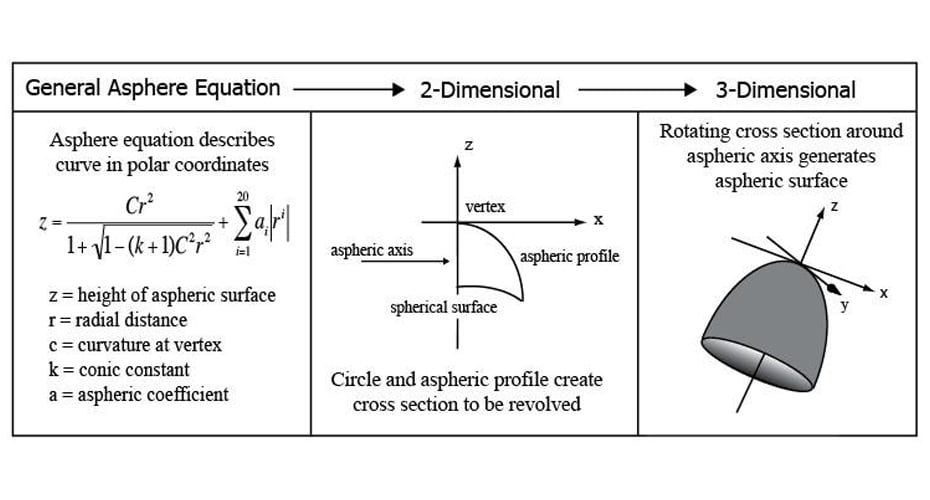 Figure 1
Aspheric elements are able to minimize aberrations caused by and inherent to spherical optical elements. Fewer elements are needed, making systems smaller, lighter and shorter. For applications where weight is primary concern, space borne applications for example, aspheres are desired.
2. SPECIFYING AN ASPHERIC LENS
Specifying an asphere begins with material selection and specification of diameter, thickness, cosmetics and clear aperture in the same way a spherical lens would be specified. The same style of tolerancing applies for these attributes as they would for a spherical lens. There are many complete guides available1,2.
After that, a custom aspheric form, fit to the General Aspheric Equation, is specified for a surface. The objective is to null out a specific set of residual aberrations present in an all-spherical system. Each asphere is custom to the correction it is to perform. Specifying form involves specifying Vertex Radius, Conic Constant and applicable Aspheric Coefficients.
Tolerancing form error for an asphere is similar to tolerancing a combination of spherical power and irregularity, showing deviation from ideal form. Instead of showing power, a tolerance on the vertex radius is given.
Centration errors can destroy lens performance. Critical consideration must be given to method of manufacture and measurement.
3. MANUFACTURING CONSIDERATIONS -DEPARTURE DRIVES PROCESS
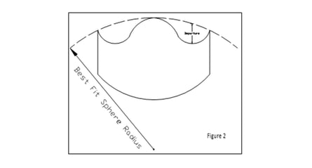
Asphere manufacturing starts with the same considerations made in manufacturing any optical component. Material, diameter, aspect ratio, form accuracy and finish quality are considered as they would for any optical element3. The differentiating consideration is that of Best Fit Sphere (BFS), the spherical radius that encloses the aspherical profile. Even the most extreme aspheric profiles have a BFS, as illustrated in Figure 2 below. The maximum distance vertically between the BFS and the aspheric profile is the aspheric departure. BFS and the aspheric departure have the biggest influence on process selection.
Aspheric departure drives process selection.
 It’s not only the total departure that matters, but rather the rate of change in departure that matters. An aspheric departure of 25 µm spread uniformly over a 100mm diameter is less challenging than the same 25 µm located all in the last 5mm in from the edge or another narrow zone.
There are three main processing options in use at Optimax, and the departure of the asphere has the main influence on choice.
- Polish In Asphericity
Optimax may polish mild (<10 µm uniformly distributed) departures into a spherical part. - Fine Grind In Asphericity
As departure, more specifically rate of change in departure, increases, Optimax will fine grind and then polish in the asphericity. This option would be selected for departures of 10 to 50 µm of departure. - Rough and Fine Grind In Asphericity
This is reserved for all remaining amounts of asphericity. It is similar to the Fine Grind process, adding a rough grind prior to the fine grind and polish.
4. METROLOGY CONSIDERATIONS
The three main metrology options are listed below, and some detail of each is given. Each possessing its own benefits and restrictions, they are arranged in order of increasing complexity and subsequently cost.
Profilometry
This is the most commonly used metrology option for aspheric forms. The device measures height of the surface as a function of movement along one axis, producing a 2-D table of data. Using information about the ideal form and how the profilometer is set up, the data is analyzed, showing error from theoretical form with setup related tilt removed.
Interferometry in Reflection
Reflective interferometry for aspheres works in the same manner as spheres or flats, except the null target is unique to the specific desired ideal aspheric form. Lenses that may be measured interferometrically can be specified in the same manner as any spherical surface, with a linear tolerance on the vertex radius and the irregularity as the deviation from aspheric form. Power may also be used, and Optimax would convert the resulting sag difference into a linear tolerance.
There are three techniques here, on-axis measurement for mildest forms, subaperture stitching for more complex forms and holographic testing for the most complex forms.
On-axis Measurement
For some cases the asphericity is mild enough where an interferometer is powerful enough to see through the aberrations present. This process is typically reserved for aspheres of less than < 10µm of aspheric departure and < 150mm of diameter. Allowable departure is proportional to diameter.
Subaperture Stitching
More departure can be handled by stitching interferograms together. Using QED’s Subaperture Stitching Interferometer (SSI) or Zygo’s VeriFire AT mild aspheric forms can be formed using conventional transmission spheres. While moving the part until the local curvature becomes manageable, several (ranging from ~5 to ~100) overlapping measurements are made. A full aperture representation of the deviation of the aspheric surface is formed by stitching the measurements together. Broadly speaking the present limit is < 50µm of aspheric departure and < 200mm of diameter. Allowable departure is proportional to diameter.
Holographic Testing
Interferometric testing is still possible for larger departures using a holographic null, a custom diffractive optical element which generates an appropriate null wavefront for the asphere to be tested. Each aspheric form would need its own null, each costing about $10 – 15K and taking about 10 – 15 weeks to get.
Interferometry in Transmission
For aspheric lenses, there are some specific cases where testing in transmission as opposed to reflection offers a simpler solution. It is possible with one simple null assist optic or even none at all an asphere may be tested, saving time and money over reflectance testing. This is an extreme special case. The test measures literal transmission wavefront error (TWE), looking at the sum of all errors. It sums up the contributions from errors in centration, form and material. This sum is targeted and corrected.
5. CONCLUSIONS
- Aspheres are specified using the General Aspheric Equation
- Aspheres are designed to null out a unique set of aberrations
- The manufacturing process is a function of the best fit sphere (BFS) and departure
- There are many metrology options, with selection driven by departure, form error and cost objectives
References
[1] W.J. Smith, Modern Lens Design, Ch 23, McGraw Hill, New York City, 2005
[2] R.E. Fischer, B. Tadic-Galeb, P. Yoder, Optical System Design, Ch 16, McGraw Hill, New York City, 2008
[3] R.E. Fischer, B. Tadic-Galeb, P. Yoder, Optical System Design, Ch 18, McGraw Hill, New York City, 2008
Optimax Systems, 6367 Dean Parkway, Ontario, NY USA
©Copyright Optimax Systems, Inc. 2009